In this post we will go through the process of writing a custom STM32303RE bootloader. We will use the reference manual to find out all relevant details and use STM32CubeIDE for development. The actual board used during the development is STM32 Nucleo-64 board. Reference manual for the MCU can be found here.
Flash memory organization

The reference manual states the following:
The memory organization is based on a main memory block containing 128 pages of
2 Kbytes in STM32F303xB/C and STM32F358xC devices, 256 pages of 2 Kbytes in the
STM32F303xD/E and an information block as shown in Table 7. In STM32F303x6/8 and
STM32F328x8 devices the memory block contains 32 pages of 2 Kbytes.
What does this means for us. It means that when we start writing our custom bootloader, we will need to occupy multiple of 2KiB for our firmware. For our need, we will occupy only the first 12Kib in range (0x0800 0000 – 0x0800 2FFF), and leave the remaining flash to application firmware.
Startup procedure for ARM Cortex-M4 MCU
Before we start writing the bootloader, we need to understand how the MCU actually gets to our main(void) function. To understand this we need to refer to ARMv7-M Architecture Reference Manual.
B1.5.3 The vector table
On reset, the processor initializes the vector table base address to an IMPLEMENTATION DEFINED address. Software
can find the current location of the table, or relocate the table, using the VTOR, see Vector Table Offset Register,
VTOR on page B3-657.
Address of the VTOR register is 0xE000ED08. The proof is show below.
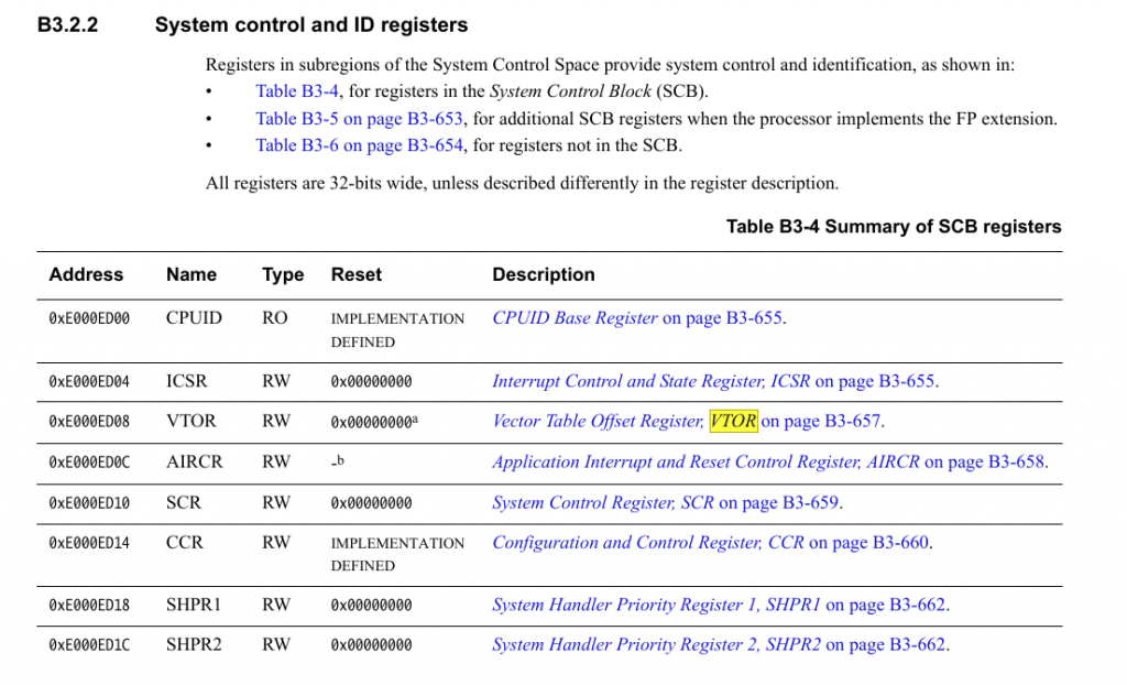
Strange thing here is that we have somewhat confusing documentation regarding the default value. B3.2.2 states that it’s implementation defined, and SCB register table says it is 0.Let’s look at the actual value of the register in the debugger.
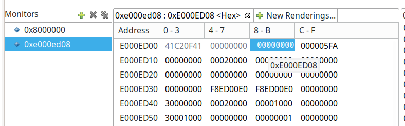
We can see that the actual VTOR register contains value 0. But how can this be since our flash is starting from address 0x08000000. To answer this section we need to open reference manual of the actual MCU.
Boot from main Flash memory: the main Flash memory is aliased in the boot memory
space (0x0000 0000), but still accessible from its original memory space (0x0800
0000). In other words, the Flash memory contents can be accessed starting from
address 0x0000 0000 or 0x0800 0000
So it seems that the address 0x0000 0000- is alias of flash starting at address 0x0800 0000.
Let’s actually check this by comparing addresses 0x0000 0000 – 0x0000 0000F and 0x8000 0000 – 0x8000 000F
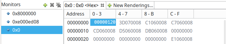
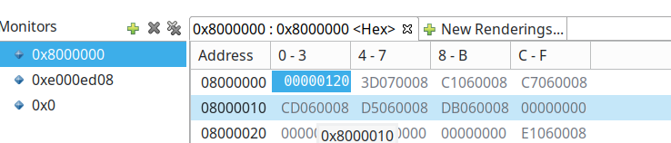
It looks like it is the same, and the address 0x0000 0000 is addressable from the MCU as stated in the reference manual.
The execution plan
To realize this project we need to create a list of tasks that we need to perform in order to realize our bootloader. Here are the bullets.
- Update linker script to force place all our code in first flash page
- Update main function to do:
- Adjust VTOR register to point to second flash page
- Load our reset function pointer address from new VTOR and jump to it
Update linker script to force place all our code in first flash page
Linker script reflects the memory map of the MCU. Since the IDE already created the full linker script we do not have to do much except to change MEMORY segment.
Original map:
MEMORY
{
  CCMRAM    (xrw)    : ORIGIN = 0x10000000,   LENGTH = 16K
  RAM    (xrw)    : ORIGIN = 0x20000000,   LENGTH = 64K
  FLASH    (rx)    : ORIGIN = 0x8000000,   LENGTH = 512K
}
Modified map:
MEMORY
{
  CCMRAM    (xrw)    : ORIGIN = 0x10000000,   LENGTH = 16K
  RAM    (xrw)    : ORIGIN = 0x20000000,   LENGTH = 64K
  FLASH    (rx)    : ORIGIN = 0x8000000,   LENGTH = 12K /* now 12K */
}
Update main function
Main function should now adjust VTOR register to reflect the new vector table location.
We need to to this because our application firmware has it’s own list of interrupt handlers shipped. If we left the bootloader vector table as default vector table, all interrupts configured by our application would not be triggered.
Original main function:
int main(void)
{
  /* USER CODE BEGIN 1 */

  /* USER CODE END 1 */

  /* MCU Configuration--------------------------------------------------------*/

  /* Reset of all peripherals, Initializes the Flash interface and the Systick. */
  HAL_Init();

  /* USER CODE BEGIN Init */

  /* USER CODE END Init */

  /* Configure the system clock */
  SystemClock_Config();

  /* USER CODE BEGIN SysInit */

  /* USER CODE END SysInit */

  /* Initialize all configured peripherals */
  /* USER CODE END 2 */

  /* Infinite loop */
  /* USER CODE BEGIN WHILE */
  while (1)
  {

    /* USER CODE END WHILE */
    /* USER CODE BEGIN 3 */
  }
  /* USER CODE END 3 */
}
Modified main function:
int main(void)
{
/* USER CODE BEGIN 1 */
/* USER CODE END 1 */
/* MCU Configuration--------------------------------------------------------*/
/* Reset of all peripherals, Initializes the Flash interface and the Systick. */
HAL_Init();
/* USER CODE BEGIN Init */
/* USER CODE END Init */
/* Configure the system clock */
SystemClock_Config();
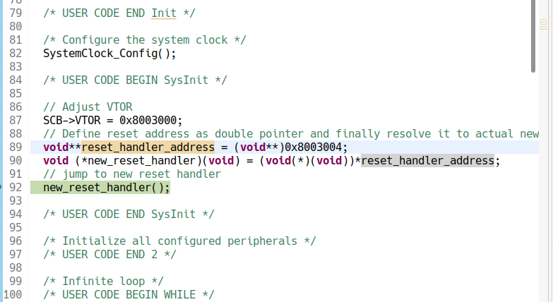
/* USER CODE BEGIN SysInit */
// Adjust VTOR
SCB->VTOR = 0x8003000;
// Define reset address as double pointer and finally resolve it to actual new reset handler.
void**reset_handler_address = (void**)0x8003004;
void (*new_reset_handler)(void) = (void(*)(void))*reset_handler_address;
// jump to new reset handler
new_reset_handler();
/* USER CODE END SysInit */
/* Initialize all configured peripherals */
/* USER CODE END 2 */
/* Infinite loop */
/* USER CODE BEGIN WHILE */
while (1)
{
/* USER CODE END WHILE */
/* USER CODE BEGIN 3 */
}
/* USER CODE END 3 */
}
Now we simply need to compile and download the code to board. The code itself wont do anything since we do not have our application starting at address 0x0800 0300.
Creating new project for our firmware that will be kick-started by bootloader
Let’s create new project with out STM32CubeIDE and do some modifications before uploading the actual code to MCU.
Let’s update our link script memory block from
MEMORY
{
  CCMRAM    (xrw)    : ORIGIN = 0x10000000,   LENGTH = 16K
  RAM    (xrw)    : ORIGIN = 0x20000000,   LENGTH = 64K
  FLASH    (rx)    : ORIGIN = 0x8000000,   LENGTH = 512K
}
to following values:
MEMORY
{
  CCMRAM    (xrw)    : ORIGIN = 0x10000000,   LENGTH = 16K
  RAM    (xrw)    : ORIGIN = 0x20000000,   LENGTH = 64K
  /* before was   FLASH    (rx)    : ORIGIN = 0x8000000,   LENGTH = 512K */
  FLASH    (rx)    : ORIGIN = 0x8003000,   LENGTH = 500K
}
Let’s also modify the main function so that we get a visual indication form it (green led flashing).
int main(void)
{
  /* USER CODE BEGIN 1 */

  /* USER CODE END 1 */

  /* MCU Configuration--------------------------------------------------------*/

  /* Reset of all peripherals, Initializes the Flash interface and the Systick. */
  HAL_Init();

  /* USER CODE BEGIN Init */

  /* USER CODE END Init */

  /* Configure the system clock */
  SystemClock_Config();

  /* USER CODE BEGIN SysInit */

  /* USER CODE END SysInit */

  /* Initialize all configured peripherals */
  MX_GPIO_Init();
  MX_USART2_UART_Init();
  /* USER CODE BEGIN 2 */

  /* USER CODE END 2 */

  /* Infinite loop */
  /* USER CODE BEGIN WHILE */
  while (1)
  {
	  HAL_GPIO_TogglePin(LD2_GPIO_Port, LD2_Pin);
	  for(int i = 0; i < 1000000; i++);

    /* USER CODE END WHILE */


    /* USER CODE BEGIN 3 */
  }
  /* USER CODE END 3 */
}
Everything else should be the same. We now just need to compile and download the firmware to our MCU.
How do we know that bootloader is working?
Let’s get back to bootloader project and debug the firmware. Since the bootloader does not have led code (no blinking), if the board starts blinking, we know that application flash is unchanged and that our bootloader jumped to application firmware main function.
After we resumed the code, board started blinking – our bootloader is working!