When I was learning USB 2.0 I struggled with some concepts because a lot of things need to be remembered without having any usable visualization tool. I looked at Beagle board and similar devices, but because of their cost they were out of my reach. At some point I decided to get a relatively cheap logic analyzer with supported sampling of up to 1Ghz which opened a window for inspecting and visualizing the actual traces and finally understanding all the bits and pieces of USB protocol (control, bulk and interrupt transfers).
USB is a master/slave bus, where master is called a USB host and device a is a USB device.
In USB host is initiator of all communication and is aware of all connected devices.
Most basic unit of transfer blocks
Most basic building block in USB is something called a packet. There are many kinds of packets, and they are identified by something called PID or packet identifier. What follows after pid is completely determined by the PID value.
PID is a 8 byte value where first nibble is the actual identifier and last nibble is the essentially redundancy check value used to validate the first nibble.
Possible PID values are:
| Name | Value | Used by transfer types |
|---|---|---|
| OUT | 0001 | all |
| IN | 1001 | all |
| SOF | 0101 | Start of Frame |
| SETUP | 1101 | control |
| DATA0 | 0011 | all |
| DATA1 | 1011 | all |
| DATA2 | 0111 | isochronous |
| MDATA | 1111 | isochronous, split transactions |
| ACK | 0010 | control, bulk, interrupt |
| NAK | 1010 | control, bulk, interrupt |
| STALL | 1110 | control, bulk, interrupt |
| NYET | 0110 | control, bulk OUT, split transactions |
| PRE | 1100 | all |
| ERR | 1100 | all |
| SPLIT | 1000 | all |
| PING | 0100 | control write, bulk OUT |
| EXT | 0000 | – |
With our understanding of PID header, let’s cover the end of packet. End of packet is indicated by special signalling implemented withing the host or device controller. This means that the length is not stored within the packet and is defined by marker which is not seen by our packet reading/processing code.
Now, let’s look at few logic analyzer captures of USB packets.
Start of Frame Packet
Start of frame is a special packet transmitted by USB Host. It is usually used as a mean of synchronization and is transmitted every millisecond and contains a frame number.
Let’s look at the example of such packet
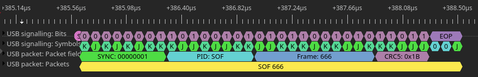
From the picture we can deduce that frame starts with SYNC signalling pattern, followed by SOF PID byte, 11-bit frame number, CRC-5 value and finally ends with EOP signalling pattern.
When using Bulk transfers within firmware and libusb I did not have to specifically use any synchronization so I can’t tell more about it than to search the web for more info.
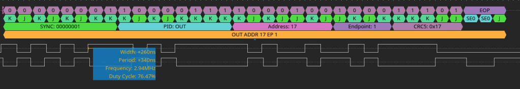
Setup Packet
Setup packet is a special packet used during Control Transfers. Control Transfer is the the transfer type which needs to be supported by all devices and is used during the enumeration/configuration process.
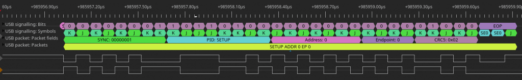
Here we can see the sample of decoded Setup Packet, and first thing that we notice is that it’s more structured than plain SOF Packet. It starts with SYNC signalling pattern, PID byte, 7-bit address, 4-bit endpoint, 5-bit CRC and ends with EOP signalling pattern.
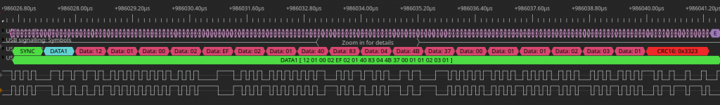
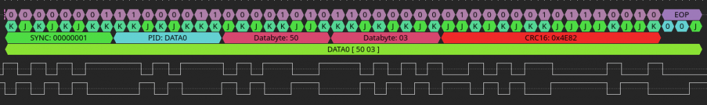
DATA0 Packet
DATA0 packet is used to transfer actual data from host to device or vice-versa. It’s meaning usually depends on context and previously used packet (IN, OUT or SETUP).
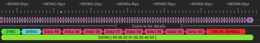
DATA0 packet starts with SYNC signalling pattern, followed by PID byte, 8-bytes of data, 16-bit CRC and ends with EOP signalling pattern. The size of DATA0 packet size is determined by EOP pattern; it is not carried as a value withing the packet.
DATA1 Packet
The meaning of DATA1 packet is the same as DATA0. The purpose of having DATA0 and DATA1 is to toggle data synchronization. If the reader sees two DATA0 or DATA1 packages in succession, it means that it skipped one DATA packet.
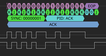
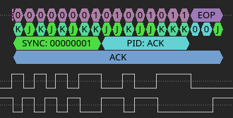
ACK Packet
ACK Packet is a special kind of packet which only carries a that a previously received packet (usually DATA, IN or OUT) was successfully received.

ACK packet starts with SYNC signalling pattern, followed by PID byte and ends with EOP signalling pattern.
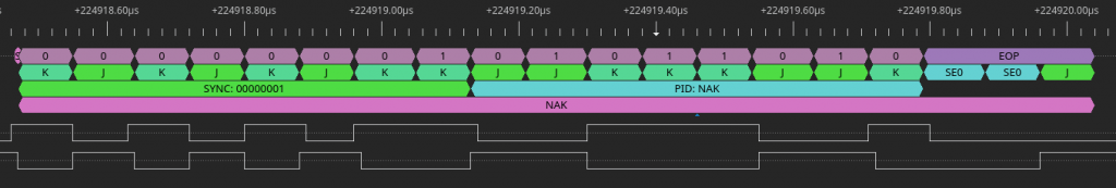
NAK Packet
NAK (negative acknowledge) means the device is busy or has no data to return . If host sends data to device which is busy doing something else, the device may simply return NAK. In the case where hosts requests data and device does not have any, the device also may return NAK.
This is a number of accepted NAK returns is limited and is defined either by driver or by USB descriptor config. Host MUST never returns NAK.
Transfer Types
USB defines 4 kinds of transfer types:
- Control transfer
- Bulk transfer
- Interrupt transfer
- Isochronous transfer (not covered here)
Control transfers
This transfer type carries standardized request structure that needs to be supported by every USB device.
Device may also support custom protocol over this transfer type.
Every device need to pin endpoint 0 to Control transfer, but may also use other endpoint for custom-purpose control transfer.
Every host allocates a fixed bandwidth for control device which is not expanded if device has additional Control transfer endpoints.
Setup stage
Setup stage consists of SETUP package, followed by DATA package and ACK/NAK packet.

Data stage
Data stage consists of one or more IN&OUT transactions, depending on kind of setup stage.

Data size
| Bus Speed | Maximum Data Packet Size (bytes) |
|---|---|
| Low speed | 8 |
| Full Speed | 8, 16, 32, or 64 |
| High Speed | 64 |
These bytes include only information transferred, excluding PID and CRC bits.
Also , in Data stage all packets except last one (Data packet) must be of maximum size for endpoint.
If the the actual payload is multiple of maximum size, than last packet must be Zero Length packet.
Status stage
Status stage consists of one IN or OUT transactions where the device reports success or failure of the whole transfer.
Outstanding conditions
If device sees new Setup stage in between existing Transfer, it must discard existing operation, and start processing new control transfer.
Recap
So, Control Transfer consist of one Setup stage, followed by zero or more data stages and one status stage.
ControlTransfer :== SetupStage, DataStage*, ControlStageBulk Transfer
Bulk transfer is most useful to transfer data into and out of USB device. It’s not real-time transfer, so because of that it’s not intended to be used for transferring audio, video or other time-sensitive data streams. Ideal use cases are data transfers which can very in latency and bandwidth (USB disk drives, printers, Smart Cards, etc…).
USB Low speed devices do not need to support bulk transfers, and in general devices are not required to support bulk devices if they use protocol not needing such functionality.
Bulk transfers consist of IN or OUT transactions, and the end is reached when the transaction transmits number of bytes less than maximum defined number of bytes that each transaction can transmit.
Bulk transfer transaction
Bulk transfer transaction consists of one IN or OUT packet, one or more DATA packets and final Handshake packet.
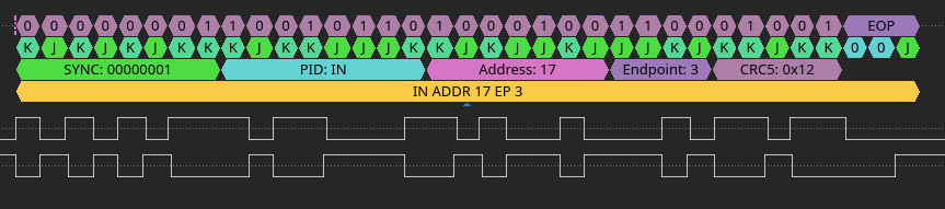
IN Transaction Example
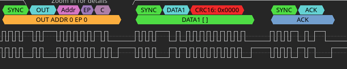
OUT Transaction Example

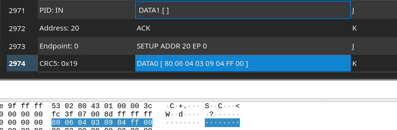
Correlating DSView Endianess with WireShark
There is no interpretation of bytes by WireShark, so byte stream is as it’s repoted.